

AutoPole Test Drive
This innovative prism pole, the first of its kind with tilt compensation, auto-height, and target identification, does not disappoint.
Spoiler: it worked very well.
Leica Geosystems (part of Hexagon) announced the AP20 AutoPole in March of 2022, and I was quite eager to get my hands on one to try it out. Through decades of robotic total station use, dealing with some major sources of user error I do not think I was alone in hoping that someday, someone would develop a prism pole with tilt to ease the frustration and potentially boost productivity.
I’m going to say this upfront as there will be inevitable negative reactions to this, as with any other new surveying tech announced. Yes, absolutely, such tools will only work to their full potential in the hands of careful and diligent practitioners. And yes, absolutely, one should not trust anything blindly. But like almost any other tool, you can easily test for effectiveness and reliability. No one is advocating the use of new tech to promote sloppiness; in the right hands, such tools can deliver the precision and reliability your projects require and help reduce common sources of error.
By sources of error, I mean the big three inherent to total station operation: locking on the wrong target, incorrect pole height, and the tyranny of the bubble. Certainly, diligence in use can reduce instances of such error, but it was an inevitability that some of these functions would be automated, and if they can perform as designed, bring productivity gains. Right now, is a prime time to increase productivity. Who knows how long this current peak in projects will be with us? But while it is, there is a lot of work—in some places, much more than many firms can take on (with legacy tools and methods). Increased productivity could the key to being competitive and taking advantage of these peak times.
Test Drive
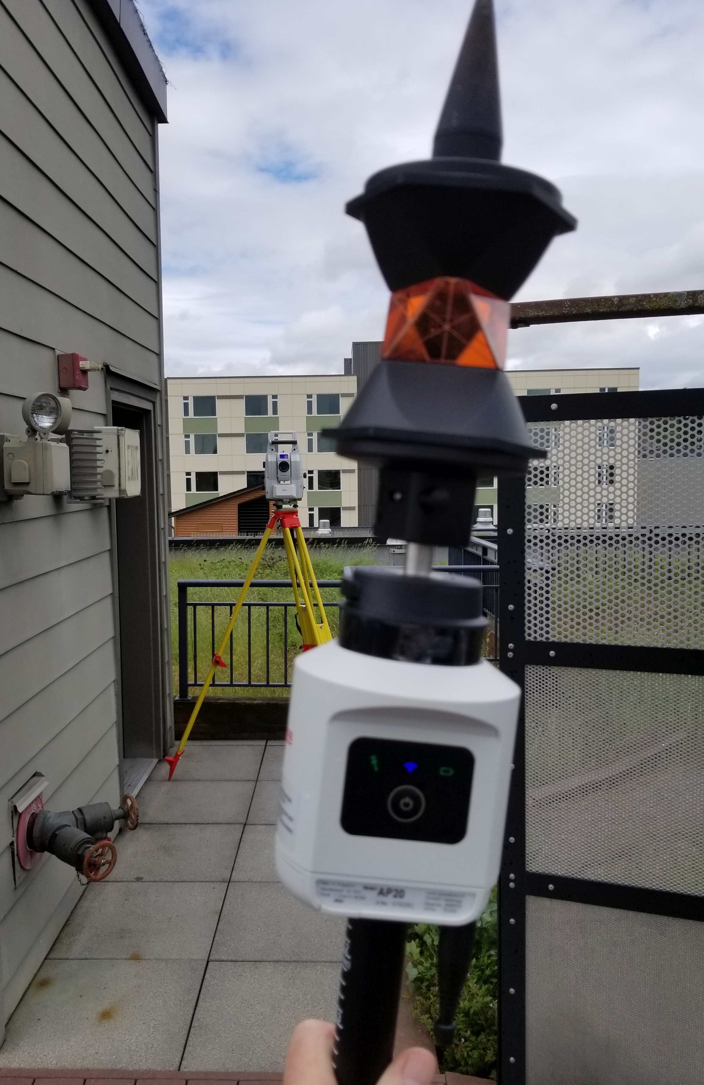
I borrowed an AP20 from Kuker-Ranken, a prominent construction and surveying equipment supplier covering many of the western U.S. states. Rob Mitchell from K-R brought an AP20 AutoPole, and an MS60 total station to a test site I’ve set up on the roof of my building. Over the course of several years, I’ve test driven a lot of surveying equipment up there, including the Leica GS18 I; a GNSS rover with tilt and image point capabilities. I’ve surveyed and scanned this site (several times), so it was easy to check positional results, and time used compared to more conventional methods. It rained steadily each day (it was Seattle in June after all), so it was a chance to test the fog/mist/rain target tracking setting.

The test drive included shooting test points, in tilt and plumbed pole mode. And repeating topo conducted previously with other equipment; also comparing to scans of the same.
There’s a lot of glass and shiny fixtures on the test site and surrounding buildings, which can cause target lock issues for some past systems I’ve tried. Plus, there are several small prisms that had been installed on adjacent structures for various construction projects. This proved to not be a problem for the MS60 and AP20 AutoPole; but more on that later.
Tilt Function
Much like the no-calibration tilt compensation on the GS18 T and GS18 I, the tilt function could represent the most potential for productivity gain from the AP20. Even if you keep your rod bubbles properly, and frequently calibrated, the amount of extra time spent to manually “bubble up” for each shot is not really apparent until you’ve started working with a tilt-compensated system.
Once the AP20 is connected to the total station, a brief circular movement of the pole for the first shot initializes the tilt, as indicated by the green tilt status light on the unit. For subsequent shots, incidental movment of the pole moving between points was sufficient to keep the tilt active.
When using tilt-compensated GNSS for some tasks like straight-up topo, I’ve seen gains of 20%-40% over bubble-based operation, as have others I’ve spoken to. But the AutoPole takes this even further as you can pick up shots in places the GNSS simply cannot; like sky-view obstructed areas and especially indoors. And ironically in many cases, for shots a GNSS system cannot get, you would have had to pull out a total station to shoot them.
How it works seems counterintuitive at first: how can you get a stable position from a moving prism? An amusing way to look at this is that it turns Heisenberg’s Uncertainty Principle–that it is difficult to determine both the momentum and position of a particle— on its head, in that tilt compensation finds stability from motion. While this prism pole tilt shares a lot in common with GNSS+IMU tilt compensation, it derives the trajectory of the target not from GNSS, but in constant tracking by the total station.
Once the tracking is set up, and the total station confirms the target, you move the pole around and the total station tracks continuous positions, giving a trajectory. The IMU continuously measures the pole acceleration and the angular rates. The tilt and tilt direction are then basically derived from the attitude measured by the IMU; together these provide a position for the tip of the pole.
There are a few more steps in the workflow than with a standard pole to get it all working, but once set up, smooth sailing. There is a bubble on the pole; check it and the straightness of the pole as you would with any other pole. Set up the total station the same way as you would for any normal operation. Then you turn on the AP20, connect it through a setup wizard in the Captivate software on the controller, set up target ID (if you opt for that feature), and enter the rod height (or this will be populated automatically if you have the auto height option).
You start to measure and select start tilt. You have to move the rod around a bit to initialize it; keeping the tip in place, I moved the rod in a circular motion recommended by the product team. Once initialized, a green indicator on the AP20 lights up, then you are good to go. It will tell you if it loses tilt; like if you hold it still for 10 seconds or so. Sometimes it keeps the tilt longer than that; seemingly the longer I’d been moving it around in the course of the survey, the longer it would keep tilt when held still. I’d like to experiment a bit more with that, but the point (no pun intended) is kind of moot; the pole moves around enough moving from point to point that I did not have to add any extra movement.
Tilt Precision
The documentation for the MS60 and TS16 total stations (those supporting AutoPole operation) has new sections for the AutoPole. It gives precision estimates for different tilt angles at different rod heights. For instance, with a 2m rod you should see 4mm + 0.7mm/° tilt in horizontal, and 1mm +0.1mm/° tilt in vertical. 30° should vary from a shot with plumbed rod by 25mm horizontal and 4mm vertical. I did most of my test shots with the rod set at 6’, and did plumb shots, 5°, 15°, 30°, and 45°. Inversing individual plumb shots and associated tilt shots consistently matched the precision estimates—most came out better.
Once I got feel for what error to expect at different tilt angles, I walked though some simple topo; essentially repeating sections of the site I’d surveyed with other gear. It took about half the time to do the same section with tilt as it had with a total station and “bubbly rod”—can I coin that term? It took just over half the time as a previous survey. Likely this will vary a lot, and my test was done on familiar ground. I did another section of the site—same results. I later looked at all points shot in a model I have with points from previous tests and scans; things lined up quite well. I looked at the point data and noticed that nearly all points I took in tilt mode, just moving around the site and taking shots as needed, did not exceed 5° of tilt. Comparing those to plumbed shots on the same points, the precision was under a cm as predicted. I have never known Leica (or other major surveying equipment manufacturers) to exaggerate estimated precisions; if anything, they seem a bit conservative in their published specs.

I tested the inverted pole configuration by adding a pole tip to the thread on the 360 prism. With the short distance between the tip and center of prism, the precision difference between plumbed pole and tilted pole results was negligible.
Then I did stakeout on some of the same points. As I had found when using a GNSS rover with tilt compensation, doing stakeout with the AutoPole is quite slick. No more stop-plumb-look-repeat-repeat-aaargh! You can just move the tip around and look at the controller to see when it hits the point.
I tried the option of inverting the AutoPole, so that the AP20 and prism were at the bottom, attached a pole tip to the prism, measured up to the center of the prism, and entered that manually as a (negative) value in the tilt settings. There is also a software setting available which enables the “upside down” use case and the pole height gets automatically applied. With the height so short, like at -0.2m, the estimated precisions should (according to the manual) be: 1mm + 0.1mm/° tilt in the horizontal and 1mm + 0.05mm/° tilt in the vertical. Did some of the test topo in that mode and indeed found that difference between plumb shots and tilt were negligible.
I was not sure if the system was designed for tilt beyond 90°, but I tried that out anyhow. I tipped the rod up and hit some points above my head, along eaves and on light fixtures etc. I later checked these against previous scans of the site, and the results came in per the precision estimates. The best precision from tilt would be close, to 0°, and the worst would be at 90. So, if the pole is inverted, to reach a shot over your head, the angle would also be from the vertical; completely inverted would be best, with decreasing precision up to 90°. Again, there is a software setting to apply this automatically. I verified with a Leica product team member that they had also tested this, and it is a valid use for the system. You could also add extensions, for instance to shoot inverts in maintenance holes, but you need to enter the total height manually.
I have one wish list item related to the tilt function. I’d like to see the tilt angle displayed in real-time on the measurement screen. My reasoning is that it could be helpful for the surveyor to be able to see the angle so they can keep in mind the error budget for each shot; they may not want to exceed a certain angle to maintain a desired precision. I heard from the product team that this has been suggested by others as well, so I would not be surprised to see it in future releases.
Auto Height
With conventional prism poles, entering the wrong prism height is a common source of error. Plus, there is the time needed to input or note the height. The auto height option for the AP20 eliminates the need to do this for all but few situations.

The sensors inside the pole for the auto height function are powered by an induction coil inside the Ap20 mounting sleeve.
It works only with specific poles: CRP4, CRP5, GLS51 and GLS51F. I did the test drive with a GLS51F pole, that is graduated in feet. It is in many ways a standard telescoping pole, but it has holes spaced at 5cm (or 0.2’ on the feet version), for spring loaded lock pins. There are magnets connected to the lock pins, and there are Hall effect sensors that detect the magnet position, indicating the lock position. These components inside the pole are powered by an induction coil in the sleeve of the AP20.
You can input the height manually at any time, for instances like I encountered during my test when I was shooting thorough a mesh fence. I needed to extend the pole a smidgen beyond one of the preset 0.2 increments. Easy: simply input the height for the one set of shots, and when clicked it back into a preset, the height updated accordingly. You also need to input manually when using the fully inverted configuration as previously mentioned.
How much time could the auto height save? That is difficult to say; just how much time is expended in entering new rod heights or noting them in field book. That might not add up to much in the short term, but we all have experienced time lost chasing down a bad rod height after-the-fact—reducing errors could be the biggest benefit from this option.
Target ID
There are active tracking systems that have had some form of identifier for quite some time, but this is definitely a great addition to the AP20. Again, this option addresses a common source of error: tracking the wrong prism, or other shiny objects.
There is a dark ring under the locking mechanism at the top of the AP20’; this has an array of tiny LED lights that emit a pattern that carries the unique ID of the individual unit (i.e., tied to the serial number). When you set up the target ID in the controller, you first do a Bluetooth scan for any AP20s in range, select the one with the serial number of your unit, and assign a target number (1 through 16). This means you can have up to 16 different AP20s on a single jobsite, and never have to worry about hitting the wrong one.
The setup went smoothly. I had to do a sweep to learn what targets were at the test site; there were 4 prisms from adjacent construction and a chip in a marble building façade that it kept finding, but only the one AP20. I selected it, assigned a number, and really did not have to think about it for the rest of the testing. It would consistently find and use the prism attached above the AP20. I did have a few instances where the total station seemed to get a little confused, but it was raining a lot during the testing days. The fog/mist/rain setting did help. All in all, compared to some other systems I’ve used, this option worked better at ignoring other shiny objects and identifying the intended prism.

I did some overhead shots, comparing to points previously shot by other means. These were also within the predicted precsion specs.
Development
I’m always curious about how such developments come together. I spoke with Hans-Martin Zogg, TPS business director, Leica Geosystems. “Having tilt compensation in GNSS inspired me to have this technology for total station measurements also,” says Zogg. “The tilt compensation in GNSS was slightly less complex, as the GNSS position is in the same device as the IMU. But I knew having tilt compensation on a reflector pole would significantly improve productivity, and I believed our engineers could achieve it.”
Zogg says that the workflow required working out synchronization between the position the total station derived from the prism and the IMU in the AP20. The position of the prism is transmitted from the total station to the AP20, where it is processed together with the IMU. The AP20 processor calculates the 3D orientation of the pole in the given coordinate system of the total station. The AP20 returns the attitude information back to the total station where the final pole tip position is calculated by considering the prism position, pole tilt and target height.
“When we saw the results and great user feedback from the tilt compensation in GNSS, we decided to invest and have development teams work on the solution for the total station,” says Zogg. “There were elements in common with the GNSS solution, and some of the same developers worked on both.”
Value Proposition
The reality is that working with tilt compensation means slightly lower precision than with a plumbed pole. Of course, there can be error from conventional poles as well; was the bubble calibrated? How straight is the pole? How steady is the hand of the operator? It boils down to the error budget you have for the work you are doing, balancing time and budget with the precision that would be acceptable for the job.
Potential productivity gains would vary depending on the type of work you are doing. But you can choose different configurations for different work, like inverting the rod (i.e., shorter distance between the tip and prism) for more precise layout.
When I posted about the original AP20 announcement several months ago, most of the comments were positive, but there will always be the few folks who dismiss this (and seemingly any new tools) as useless for their work, a gimmick, or something that will make surveyors lazy. Of course, such tools will not hold the same value proposition for everyone. Furthermore, the kind of productivity boost these tools can provide does not come cheap.
There are several versions of the AP20, depending on which combination of tilt, height, or ID options you choose. I did some checking around, and while I cannot completely confirm prices, it seems that if one chooses all options (tilt, ID, height), a complete setup is around $10K USD at the time of this writing, with ID-only models starting around $3K. A substantial portion of this investment is a new radio handle that is required for your total station. It has two radios: one for the controller, and one for the AP20. The total station acts as the hub and is where much of the processing is done.
At this point in time, it appears that the AutoPole is only supported for some TS16 and MS60 models as well as the iCR70/80 for construction total stations. Beyond the new radio handle required, no other changes are needed to compatible total station. All standard functions are the same; the tilt, pole height, and target ID functions are simply additions to the Captivate field software.
Certainly, this will not be a game changer for everyone. When no-calibration tilt compensation came out for GNSS rovers there was a healthy dose of skepticism, and while you can find on most new rovers, there are many folks who do not use the option. Some total station users might find more value in the ID- or height-only versions. Will it catch on? I’d say for many users doing certain types of high production surveying, it probably will, and I’d expect to see more pole automation like this in the surveying and construction equipment industry, the same way manufacturers did for GNSS rovers.
I’ll admit I’m quite jazzed as this is something I’d hoped to see for decades. But that aside, it is impressive that each of the options worked as intended and met or bettered the published specs. And I had way too much fun trying this thing out. Yes, be skeptical of any new tool, but some testing will likely impress you.
Disclaimer:
This product review was based on limited, independent testing by the author, and does not imply that users of such products will experience the same results or makes any express or implied representation that this product as being fit for any specific uses, or warranty of any kind. The author received no compensation or other considerations for this review from the manufacturer, this publication, or any other parties. This product review is not an endorsement by the author or this publication.
